2. Unified Robot Description Format URDF
Note
Refer to URDF-Tutorials and clone the URDF-Tutorials-repo if you follow the official tutorial
git clone https://github.com/ros/urdf_tutorial.git
In this chapter we will create a model of Epson SCARA Robot.
In the workspace in the src directory create a folder called Robots, where we will put all robot description packages.
// navigate to src
mkdir Robots

catkin_create_pkg epson_g3_description geometry_msgs urdf rviz xacro

cd epson_g3_description

mkdir urdf scripts rviz
Back to the workspace and compile the packages.
2.1. Launch file
The following launch file is taken from URDF-Tutorials. It have different parameters that allow it to execute different robot models.
<launch>
  <arg name="model" default="$(find urdf_tutorial)/urdf/01-myfirst.urdf"/>
  <arg name="gui" default="true" />
  <arg name="rvizconfig" default="$(find urdf_tutorial)/rviz/urdf.rviz" />

  <param name="robot_description" command="$(find xacro)/xacro --inorder $(arg model)" />
  <param name="use_gui" value="$(arg gui)"/>

  <node name="joint_state_publisher" pkg="joint_state_publisher" type="joint_state_publisher" />
  <node name="robot_state_publisher" pkg="robot_state_publisher" type="state_publisher" />
  <node name="rviz" pkg="rviz" type="rviz" args="-d $(arg rvizconfig)" required="true" />
</launch>
It execute 3 nodes: rviz, joint_state_publisher, state_publisher. In the launch file are present 2 parameters robot_description and use_gui that are need by the two nodes``joint_state_publisher`` and state_publisher. There are also 3 arguments with default values, one of them is full name of the urdf file.
The node joint_state_publisher read the urdf file from the parameter robot_description finds all of the non-fixed joints and publishes a sensor_msgs/JointState message with all those joints defined on the topic /joint_states. We set by default the parameter use_gui to true, so when the node is executed it will show a window/widget with sliders that let us control the robot joints.
The node state_publisher uses the URDF specified by the parameter robot_description and the joint positions from the topic /joint_states to calculate the forward kinematics of the robot and publish the results via tf.
Launch the display.launch file
roslaunch urdf_tutorial display.launch model:=urdf/01-myfirst.urdf
Or independently from the working direcory
roslaunch urdf_tutorial display.launch model:='$(find urdf_tutorial)/urdf/01-myfirst.urdf'
In this case the file name is the same of the default value. So in this case it can be omitted
roslaunch urdf_tutorial display.launch
Rviz files can be deleted from the launch file if you don’t have them. They can be created from rviz later. If there is no rviz file, Rviz will not show the frames neither the robot neither select the right Fixed Frame.
We will modify launch file from the tutorial in the followingway:
<launch>

  <arg name="model" default="$(find epson_g3_description)/urdf/scara.urdf"/>
  <arg name="gui" default="true" />

  <param name="robot_description" textfile="$(find epson_g3_description)/urdf/scara.urdf" />
  <param name="use_gui" value="$(arg gui)"/>

  <node name="joint_state_publisher" pkg="joint_state_publisher" type="joint_state_publisher" />
  <node name="robot_state_publisher" pkg="robot_state_publisher" type="state_publisher" />
  <node name="rviz" pkg="rviz" type="rviz" />

</launch>
Basically I change the package name, the urdf default name and delete the reference for rviz configuration file. We will back later to rviz configuration files.
I create also a scripts folder where I will create some bash file to help me executing nodes. Simply in the bash script launch.sh there is:
roslaunch epson_g3_description display.launch model:='$(find epson_g3_description)/urdf/scara.urdf'
2.2. URDF basics
URDF is an xml file that describe the geometry of a robot. URDF is a tree structure with one root link. The measuring units are meters and radians.
2.2.1. Robot
A robot is composed mainly from links, and joints.
<robot name="robot_name">
  <link>  </link>
  <link>  </link>

  <joint>  </joint>
  <joint>  </joint>
</robot>
2.2.2. Link
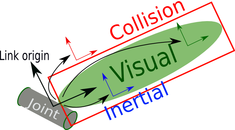
The link element describes a rigid body with an inertia, visual features, and collision properties.
The main components of link tag are as follow:
<link name="link_name">

  <visual>
      <origin xyz="0 0 0" rpy="0 0 0" />
      <geometry>
        <cylinder length="0.6" radius="0.2"/>
      </geometry>
  </visual>

  <collision>
      <origin xyz="0 0 0" rpy="0 0 0" />
      <geometry>
          <cylinder length="0.6" radius="0.2"/>
      </geometry>
  </collision>

  <inertial>
      <origin xyz="0 0 0" rpy="0 0 0"/>
      <mass value="1"/>
      <inertia
          ixx="1.0" ixy="0.0" ixz="0.0"
          iyy="1.0" iyz="0.0"
          izz="1.0"/>
  </inertial>
</link>
The visual tag specifies the shape of the object (box, cylinder, sphere, mesh, etc.) for visualization purposes.
Its origin is the reference frame of the visual element with respect to the reference frame of the link (The reference frame of the link is its joint).
The collision can be the same as visual, or its geometry a little bit bigger. Its origin is the reference frame of the collision element, relative to the reference frame of the link.
The inertial tag is need if the model is loaded in a simulator with physics engine. Its origin is the pose of the inertial reference frame, relative to the link reference frame. The origin of the inertial reference frame needs to be at the center of gravity. The axes of the inertial reference frame do not need to be aligned with the principal axes of the inertia.
2.2.3. Joint
The joint describe the relative motion between two links. It can be revolute, continuous, prismatic, fixed, floating, planar.
Basic properties of a joint tag:
<joint name="joint_name" type="continuous">
  <parent link="link1"/>
  <child link="link2"/>

  <origin xyz="0 0 0" rpy="0 0 0"/>
  <axis xyz="1 0 0"/>

</joint>
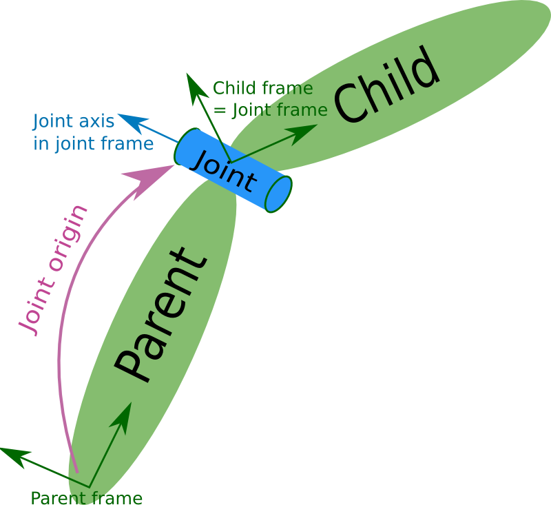
The origin is the transform from the parent link to the child link. The joint is located at the origin of the child link. So the origin is the relative position of the child frame respect to the parent frame.
The joint axis specified in the joint frame. This is the axis of rotation for revolute joints, the axis of translation for prismatic joints, and the surface normal for planar joints. The axis is specified in the joint frame of reference. Fixed and floating joints do not use the axis field.
The joint have other properties as dynamics, limit, etc. Limits are in radians for revolute joints and meters for prismatic joints and are omitted if the joint is continuous or fixed.
The following image show the relationship between two joints.
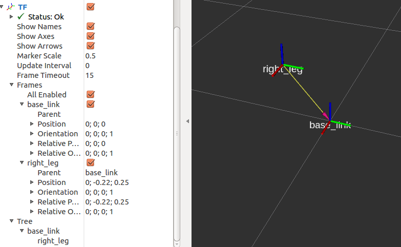
The previous image is produced by the following URDF model. Note that there is no visual aspect of the links. Only joints are defined.
<?xml version="1.0"?>
<robot name="origins">

  <link name="base_link">
  </link>

  <link name="right_leg">
  </link>

  <joint name="base_to_right_leg" type="fixed">
    <parent link="base_link"/>
    <child link="right_leg"/>
    <origin xyz="0 -0.22 0.25"/>
  </joint>

</robot>
2.2.4. Tansmission
Transmissions link actuators to joints and represents their mechanical coupling. The transmission element is an extension to the URDF robot description model that is used to describe the relationship between an actuator and a joint. This allows one to model concepts such as gear ratios and parallel linkages. A transmission transforms efforts/flow variables such that their product - power - remains constant. Multiple actuators may be linked to multiple joints through complex transmission.
<transmission name="tran1">
  <type>transmission_interface/SimpleTransmission</type>

  <joint name="joint1">
    <hardwareInterface>EffortJointInterface</hardwareInterface>
  </joint>

  <actuator name="motor1">
    <hardwareInterface>EffortJointInterface</hardwareInterface>
    <mechanicalReduction>1</mechanicalReduction>
  </actuator>

</transmission>
2.2.5. Gazebo
Gazebo can be add to different elements. Refer to the URDF-Tutorials and Gazebo tutorials. In order to simulate the model correctly in Gazebo at least he inertia and transmission tags for all links should be defined.
2.2.6. Other properties
Refer to URDF-XML and URDF-Tutorials for more information.
2.3. Complete Robot model example
2.3.1. Joint and frame definition
We will define the 3D model of Epson Scara robot G3-251s. This robot have 4 links and 3 joints.
On link is fixed, base_link. Two links rotate, we will call them link1 and link2. And the last link, link3, has translation motion.
The mechanical drawing is shown below:
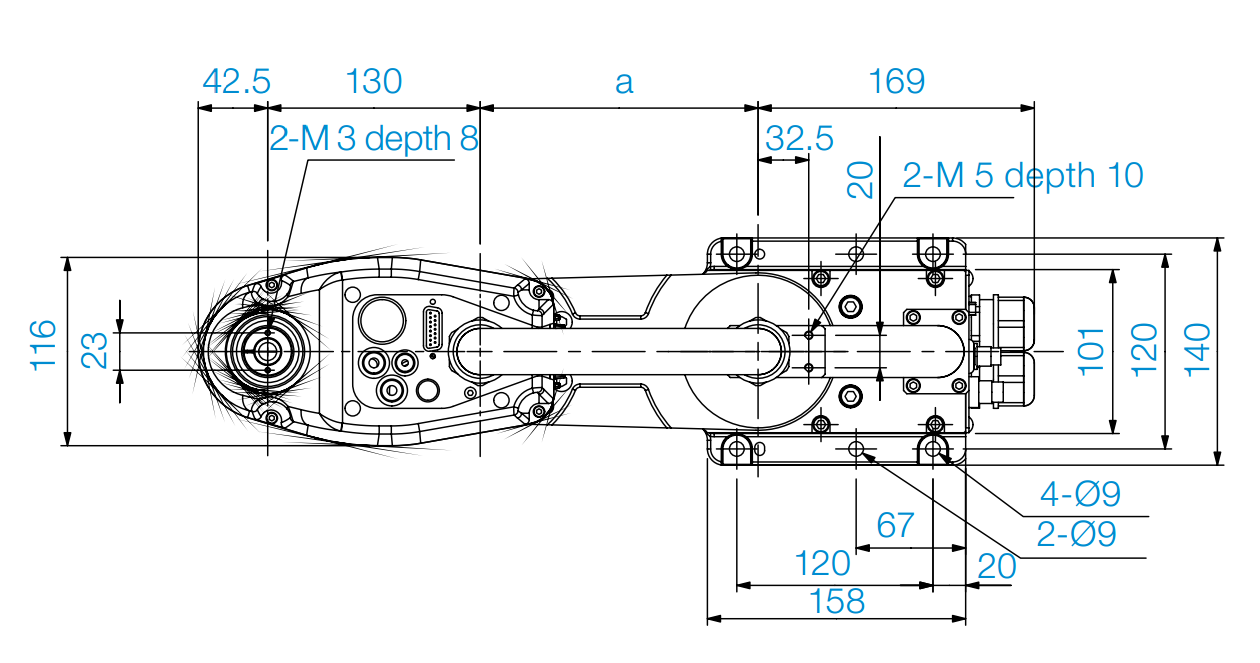
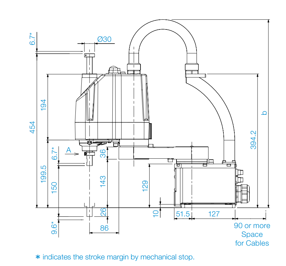
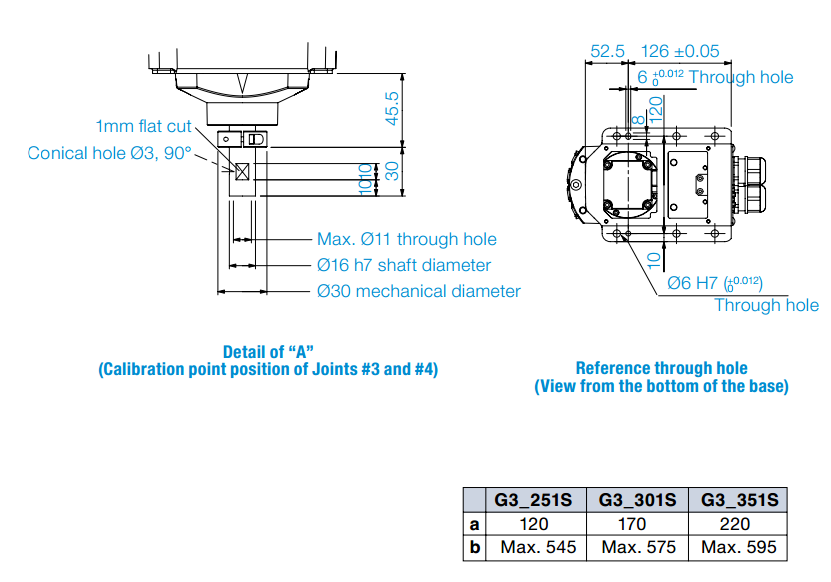
We will define first the links without visual aspect. Then we define the joints. The relative positions of the joints are taken from the previous images.
As we can see, we have 2 revolute joints and one prismatic.
First we define the links, without the visual aspect:
<link name="base_link">
</link>

<link name="link_1">
</link>

<link name="link_2">
</link>

<link name="link_3">
</link>
We define the joint_1 between the base and link1. We can define it where we want along the rotate axis. But we will define it in the contact between link1 and the base.
In zero position, all links open, the robot lie on the x axis of the base link. Joint1 has on offset in z of 129mm, so 0.129 m . The joint is define on the child link. Link1 rotate arround the z axis of joint1.
<joint name="link1_to_base" type="revolute">
  <parent link="base_link"/>
  <child link="link_1"/>
  <origin xyz="0 0 0.129"/>
  <axis xyz="0 0 1" />
  <limit effort="300" velocity="0.1" lower="-3.14" upper="3.14"/>
</joint>
In the same way we define joint2. As you can see the dimension a in the image differ from model to model. We will see later how we cam parameterize the robot model. For now we take the value for the model G3-251S, that is 120 mm.
<joint name="link2_to_link1" type="revolute">
  <parent link="link_1"/>
  <child link="link_2"/>
  <origin xyz="0.120 0 0"/>
  <axis xyz="0 0 1" />
  <limit effort="300" velocity="0.1" lower="-3.14" upper="3.14"/>
</joint>
The last joint, is prismatic. Link_3 slide along axis z. The stroke is 150mm.
<joint name="link3_to_link2" type="prismatic">
  <parent link="link_2"/>
  <child link="link_3"/>
  <origin xyz="0.130 0 0"/>
  <axis xyz="0 0 1" />
  <limit effort="300" velocity="0.1" lower="0" upper="0.150"/>
</joint>
We can use the command check_urdf to check if the urdf file have errors:
check_urdf scara.urdf
Run the launch file or run the script.
roslaunch epson_g3_description display.launch
2.3.2. Check URDF model
Navigato to urdf direcory then:
check_urdf scara.urdf
If there are no errors, you will see the parents childs tree that define the robot.
The command
urdf_to_graphiz scara.urdf
will create 2 files: scara.gv and scara.pdf.
2.3.3. Visual aspect and mesh
Espson provide CAD files in step and solidworks format. Stp can be opend on linux using FreeCad.
We need to select every link, convert it individually in stp. Pay attention to change the measuring unit. If you convert it in mm, you will see a model 1000 tmes bigger than the real robt in rviz. URDF use meter as unit. So in FreeCad change the unit in meter then export to stp. After that open the stp file and convert it to dae. In order to convert to dae the library pycollada should be installed.
Another way to convert to dae, is to convert the links in vrml using FreeCad, then open the wrml in MeshLab then convert to dae.